
In an isometric sketch of a cube Ī) The receding axes are at 45 degree to the horizontalī) the frontal face appears in its true shapeĬ) only the depth distances must be reducedġ9. Hatching lines are drawn at an angle of _.


For orthographic projection, the engineering custom bureau of Indian Standards dictates the use of: ġ7. The Top, Front and Bottom views align in this manner _. The section lines are equally spaced _ lines. _ is generally used to show areas of sections. As per recommendations of IS: 11665-1985, the LHS side margin line of a drawing sheet for class work should be kept as _ mm ġ3. In inclined lettering, the stem is inclined _ to the left. Size ‘D1’ of the drawing board refers to _ (l x w x t) mm. Sectional area is shown by hatching lines which are generally inclined at – ġ0. “Principles of folding of drawing prints” are laid down in IS: _ in India. The projection in isometric view are – ĭ) Perpendicular to the plane of projectionĨ. The recommended symbol for indicating the angle of projection shows two views of the frustum of a – ħ. Which of the following pairs of orthographic views both show the height dimension? Ħ. To lay off an angle from a given line, what marks on the protector should your align for higher accuracy- ĥ. Lettering of drawing sheet should have – Ī) In a sentence only first alphabet in capital lettersĬ) In a sentence only abbreviations in capital lettersĤ. Name the curve which has Zero eccentricityģ.

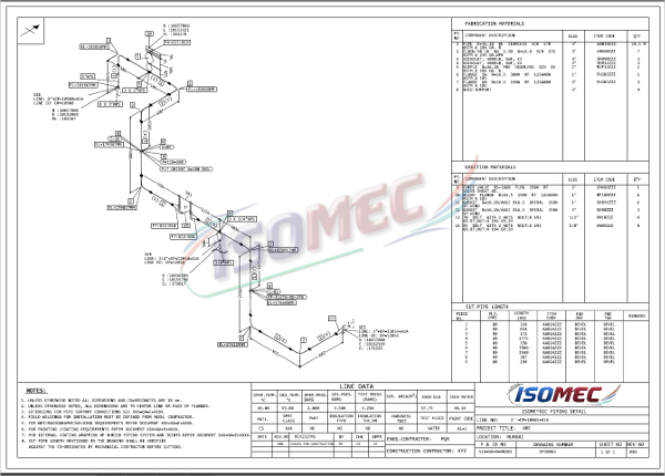
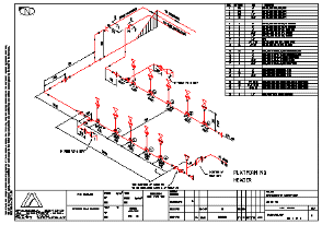
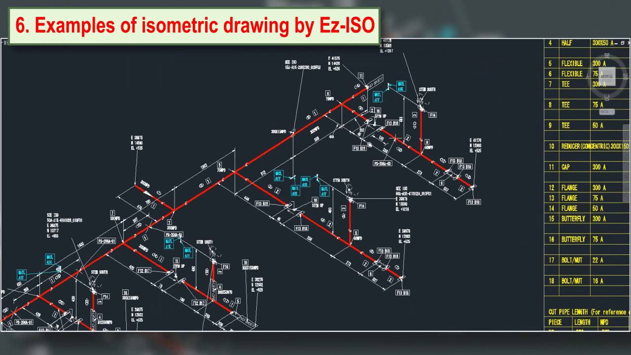
The combination of the two systems creates a productive collaboration from which machine and plant manufacturers benefit.2. Both products are among the market leaders in their fields and offer an outstanding price-performance ratio. The basic software is ISOGEN® from the market leader Alias (Intergraph). Smap3D Isometric exports all information about the 3D pipelines and creates the isometric drawing fully automatically. Smap3D Isometric for Autodesk Inventor, Solid Edge® and SOLIDWORKS® For the creation of piping isometrics we offer the integrated solution Smap3D Isometric for Autodesk Inventor, Solid Edge® and SOLIDWORKS®. Isometrics can easily be generated leveraging the Isogen® technology from ALIAS (Intergraph). We close the gap between plant, equipment and machine construction. It is much less expensive than the traditional planning systems. Our Plant Design solution is easy to install and operate. This type of drawing shows the pipeline NOT to scale and simplified with all contents and all dimensions in length, width and height, with the major axes of these three dimensions intersecting at the angle of 60°. The iso is a technical drawing in the form of an isometric representation for the production of pipelines. The third element of the typical process chain in plant construction is isometric drawings.


 0 kommentar(er)
